This page courtesy of the
Suncoast Scale model Boat Club. Back to
Bay Area Blitzkrieg.
1/16 Scale of the WPL- Hen Long "Military 4X4" [no such thing] truck (type
M35)
and Converting it to a scale model of the U.S. M34 (Reo) 6X6 Deuce-and-a-half
and Converting it to a scale model of the U.S. M34 (Reo) 6X6 Deuce-and-a-half
This page was updated on May 20, 2018 (work in progress)
Current status photos:
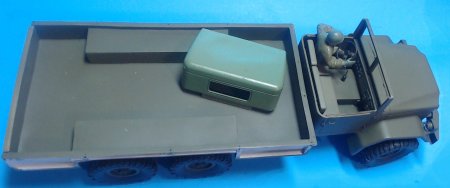
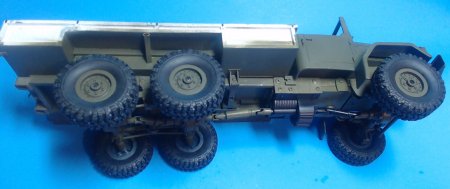
Current status photos:
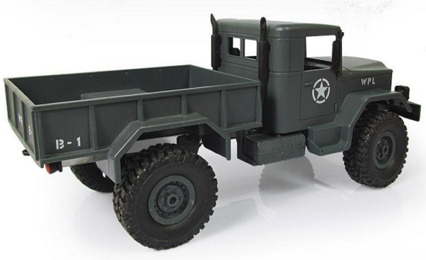
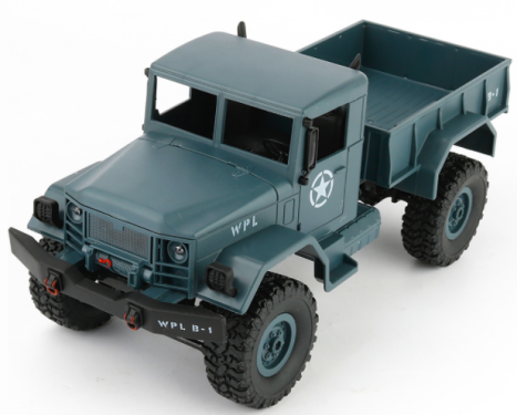
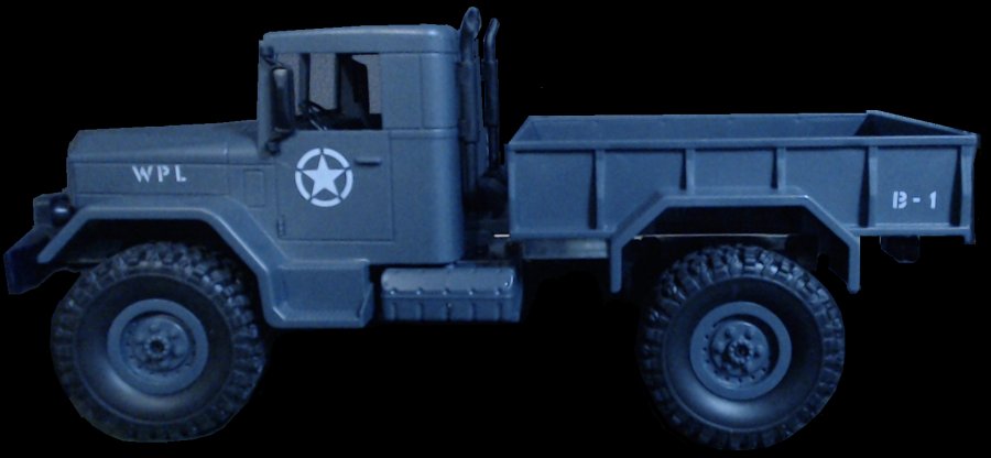
The WPL and Hen Long model wrongly
labeled "3/4 ton" US Military Trucks (WPL shown above) appear to be identical. They are a 1/16
scale "model" (somewhat accurate) radio controlled truck. They are very inexpensive and appear to be the only 1/16 scale model of this truck
made. Here we plan to rate this model as well as provide information on upgrading the model to a more scale like appearance.
Important Note: This model of this WPL or Hen Long "U.S. military truck" is not a model of a real U.S. Military 3/4 ton vehicle nor a real U.S. Military 4X4. This model is of a modified surplus truck (by private companies or individuals) into a "bobbed tail" truck for private use. This is not a model of an official U.S. Military truck.
This WPL - Hen Long truck seems to have been modeled after a civilian modified (ex-M35) M35A3 truck. The "M35A3" appears to be nomenclature created by a private business where surplus military trucks have been modified where the bed is shortened and one axle removed to make it a 4X4 for private use. Check out one company here: [Boyce].
But don't loose hope! This model can be modified to look like a deuce-and-a-half that started production after WWII (late 1940's - early 1950's). To make in look like a U.S. Military truck, modifications will need to be made. This will be described in detail as the WPL models I have are modified. When finished it will have the close (but not perfect) appearance of a U.S. model M34 2-1/2 ton truck known as the "Eager Beaver" made by Reo.
Below you will find out how to modify this WPL - Hen Long model to reasonably depict the M34 6X6 U.S. Military truck. First a look at the good and the bad points of the model. After that will be what the real trucks looked like. Lastly, a step by step procedure on modifying the model to more closely represent a late 1940's era M34 deuce-and-a-half. Although the finished model will not be exact nor be a true WWII vehicle, it could be used as a substitute where tankers could have some "2-1/2 ton trucks" in play with the tanks without going to the extreme expense or time of making a WWII CCKW truck.
Important Note: This model of this WPL or Hen Long "U.S. military truck" is not a model of a real U.S. Military 3/4 ton vehicle nor a real U.S. Military 4X4. This model is of a modified surplus truck (by private companies or individuals) into a "bobbed tail" truck for private use. This is not a model of an official U.S. Military truck.
So, what the heck is it?
This WPL - Hen Long truck seems to have been modeled after a civilian modified (ex-M35) M35A3 truck. The "M35A3" appears to be nomenclature created by a private business where surplus military trucks have been modified where the bed is shortened and one axle removed to make it a 4X4 for private use. Check out one company here: [Boyce].
But don't loose hope! This model can be modified to look like a deuce-and-a-half that started production after WWII (late 1940's - early 1950's). To make in look like a U.S. Military truck, modifications will need to be made. This will be described in detail as the WPL models I have are modified. When finished it will have the close (but not perfect) appearance of a U.S. model M34 2-1/2 ton truck known as the "Eager Beaver" made by Reo.
And, what can I do with this model to make it look accurate?
Below you will find out how to modify this WPL - Hen Long model to reasonably depict the M34 6X6 U.S. Military truck. First a look at the good and the bad points of the model. After that will be what the real trucks looked like. Lastly, a step by step procedure on modifying the model to more closely represent a late 1940's era M34 deuce-and-a-half. Although the finished model will not be exact nor be a true WWII vehicle, it could be used as a substitute where tankers could have some "2-1/2 ton trucks" in play with the tanks without going to the extreme expense or time of making a WWII CCKW truck.
Rating the stock (as purchased) model:
Pros:
Inexpensive, about $30-$35 (cost in Jan. 2018).
Perhaps a good start for modifying to be more scale looking truck.
Variable speed forward and reverse.
Ready to run four wheel drive.
Good traction with the soft rubber (oversize for scale appearance) tires.
Perhaps a good start for modifying to be more scale looking truck.
Variable speed forward and reverse.
Ready to run four wheel drive.
Good traction with the soft rubber (oversize for scale appearance) tires.
Cons
It is not an accurate scale model of this type truck
(body, tires, etc.).
Low cost means low quality, might not be too durable (spare/replacement parts are available).
U-Joints easily come apart. (The undercarriage of this model does not have the correct drive mechanism for the wheels).
Steering servo is not proportional. Seems to be a motor that continues to spin (slipping) if the steering wheel is held in one direction or the other.
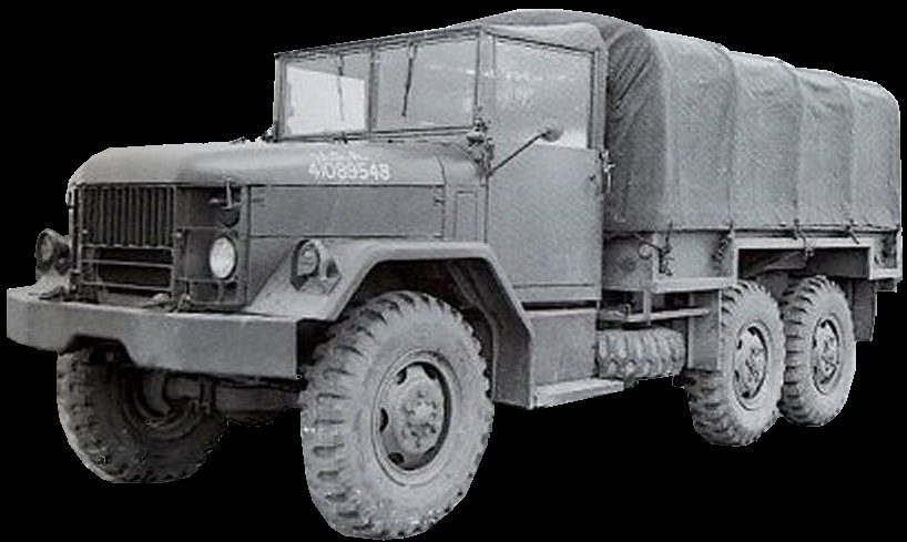
The real "M34" Series
2-1/2 Ton Trucks
The M34 series of trucks came out after WWII - in wide array of variants
and sub-variants. Engine differences could be noted by the
A1, A2, or A3 suffix, but additional suffix letters were
also sometimes added. These letters had different meanings
depending on what variant to which they were applied. You
might come across them being called the M35, M44 or M45. These were simply the chassis designation for the 2½ ton
series, and this cab/chassis would serve as the basis for
many more specialized variants.
The M34 came in 6 wheel and 10 wheel versions, both being called 6X6's. This seems to be confusing and it looks like where the dual wheels on the 10 wheel trucks were considered a single wheel.
Some websites identify the 4X4 version (four wheels) as a M35A2. This does not appear to be correct as there appears to be no four wheeled versions of this truck as built for the military. It seems a number of these trucks (six wheeled duce-and-a-half's) were cut down in length and the rear most axle removed. This is what WPL and Hen Long seems have thought was an actual U.S. military truck.
To convert the WPL- Hen Long into a WWII truck (the CCKW being the most common) the real wheels would have to be transformed into dual wheels on both axles. The entire front of the vehicle would also need to change as the look was considerably different.
Good link to see the variances: Deuce Truck Site
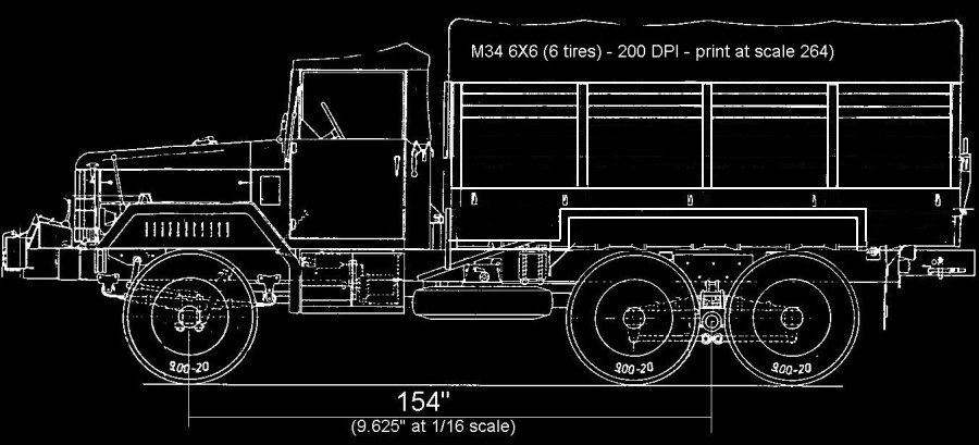
The drawing and photo above shows the comparison between a
M35 (about the same size as the M34) truck drawing and the WPL model. (It is hard to
see here, but they are fairly close.) This shows good possibilities for modifying the WPL/Heng Long model
into the Deuce-and-a-half. The tires are oversized as width
goes, but the diameters are close.
As additional parts for the model are available, an
additional axle and tires could be added. The added
axle would have to be linked to the drive, so
modifications will have to be made.
M34 6X6
Modifications to the model
Goal: To transform the
WPL - Hen Long model into a reasonably good performing
model of a M34 "duce-and-a-half". To do so,
modifications will need to be made to make the truck
operate better as well as having a close appearance of
the M34 truck without going to a lot of expense and
time. You could go a lot further, especially for
the wheels and tires.
This modifications section will be divided into to sub-sections:
This modifications section will be divided into to sub-sections:
1. Modifications to the model's body and frame
(looks).
2. Modifications to the model's radio control and electronics (performance).
Note: Allmost painting is Olive Drab. Specific area such as the exhaust pipe will require the right paint for that item.
2. Modifications to the model's radio control and electronics (performance).
Note: Allmost painting is Olive Drab. Specific area such as the exhaust pipe will require the right paint for that item.
1. Modifications to the model's body and frame
For a closer look at the WPL frame and cabin:
[Select here to view photos].
First, completely disassemble as follows:
 A
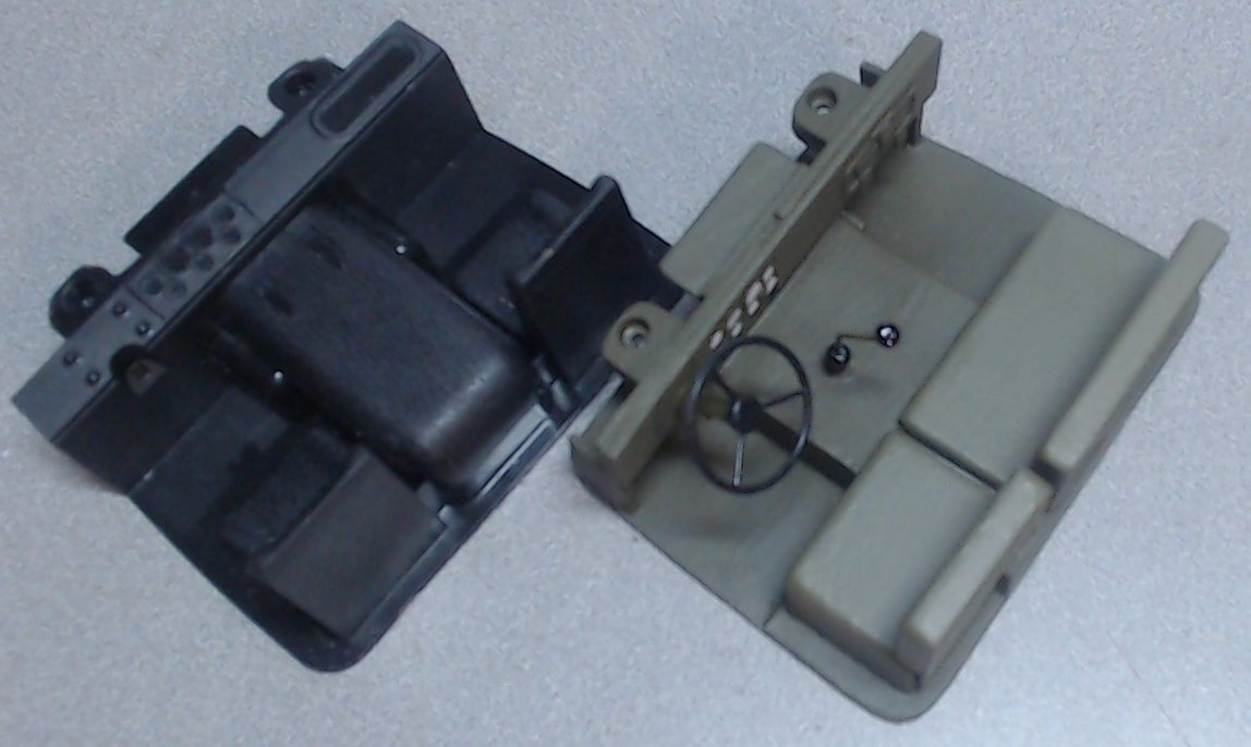
completely new interior is required to make
the "deuce" more realistic. The WPL
model is based on a modern interior
including dash board flipped up, console
over transmission, and high back bucket
seats.
A
completely new interior is required to make
the "deuce" more realistic. The WPL
model is based on a modern interior
including dash board flipped up, console
over transmission, and high back bucket
seats.
The new inerior (pictured) was made of various thicknesses styrene and has the same floor outline as the WPL model. The floor actually sits 1/4 inch lower (same seat height in relation to the cab), and an extended area under to dash for more legroom if a figure is added.
The new cabs floor over the transmission is wider than it should be to fit over the radio cear (reciever and speed control).
Paint everything Olive Drab except as follows:
- Seats slightly lighter Olive Drab for canvas finish.
- Steering wheel, shift knob, and boot black.
 Go Topless
Modify the chassis as
follows:
The chassis will require several modifications. The plastic housings for the WPL steering servo, and reciever circuit will require modification to assomocate the new serov, radio reciever, and speed controller. The chassis will also need modification for the new rear suspension (including adding the second axle).
 The
motor/gearbox should be relocated lower (but no
forward or aftward movement) by making
new side plates (copper sheet in photo).
This will not only allow the gearbox to clear
the bed, but also increase the
efficiency of the u-joints which were prone to
come apart by not having such severe angles to
the axles. This does however come a a
cost with a reduction of ground clearance.
The
motor/gearbox should be relocated lower (but no
forward or aftward movement) by making
new side plates (copper sheet in photo).
This will not only allow the gearbox to clear
the bed, but also increase the
efficiency of the u-joints which were prone to
come apart by not having such severe angles to
the axles. This does however come a a
cost with a reduction of ground clearance.
Also, see photo under: "2. Modifications to the model's radio control and electronics" (below)
Rear Axles
 With
the addition of a second axle, there are
several goals. First, the second axle
should be powered to ggive the vehicle the
maximum traction.
With
the addition of a second axle, there are
several goals. First, the second axle
should be powered to ggive the vehicle the
maximum traction.
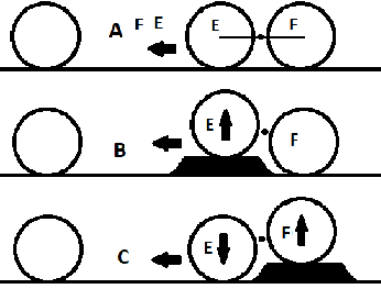
Second, the axles should act independantly of each other in the vertical direction. This can be described through the diagram at the right.
A. Moving forward on level ground.
B. A bump approaching axle C, where C rides up and D remains on the level ground.
C. As the vehicle moves forward, axle C drops down and axle D rises.
Note that this is for each side, independantly. If the bump is only on one side then the wheelset for that side moves up and down as shown and the wheels on the other side ride level.
Also note that the wheels do not ride straight up and down but on an arc where the center of the arc is the black dot between the axles. This is controlled by the suspension.
 The
following is for the drawing at the right:
The
following is for the drawing at the right:
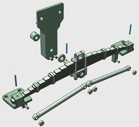
The suspension used on this model was creaded using 3D modeling and printing and is available on shapeways.com
These parts actually fasten tot he WPL axles on the ends of the springs and to the chassis (requiring 2 holes per each side). The tie-bars prevent the axles from twisting.
A second truck or spare axle purchase from a WPL retailer is required. By flipping the axle over, the wheels will turn in the same direction.
You can see where the axle pivot is, the hub under the middle of the leaf spring. The spring has a shaft which goes through a washer and into the axle mount ("T" shaped piece), then through the collar which is pinned to the shaft.
The ends of the springs mount to the axle adapters using pins on each end. The pis fit loosly through the spring to allow the axles to have some slack so the axles can act independantly in respeact to ech other.
The rear axles/wheels will now be 3.00 inches apart, center to center.
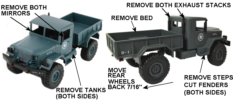
Next remove the bed (you can use this to
make a trailer later on).
Remove the cab.
Remove the "gas" tanks, both sides.
Second, completely dissassemble the cab as
follows:
Remove both side mirrors (they will be
replaced later). Remove both exhaust
stacks. Cut both fenders to remove the
steps.
Modify the cab as
follows:
Material
removal modifications to
the cab. (This will require drilling new holes.) Cut back of cab (not shown above) to be flush where the exhaust pipes turn into
the cab. DO NOT remove flanges that hold the cab on to the body, but you will need to shave a little
bit off the tops to be level with the top of
the metal chassis, as well as shaving some
material off the inner sides of the flanges
to fit over the brackets that lower the
motor/gearbox.
Make new extended fender exensions out of styrene. (Liquid hobby model kits
cement works well making a good bond between the styrene and the cab material.)
Make a fill plate out of styrene to fit the rear bottom of the cab (between the chassis
planges). Cement in place.
Remove the center divider from the rear window.
Add material (styrene) to simulat windshield hinges on each side of the windshield.
The roof and top sides
of the cab were made of canvas (on a metal
frame). To simulate the canvas you can heat the roof pushing it down slightly to make the roof "sag". You can also scribe some stretch marks in the corners. Also, you can add some snap buttons along the edge over the door windows.
Cut the side windows out further to the rear to the first scribed line (about 3/8 inch).
Scribe new lines for rear edge of doors, in line with the new window opening.
....insert photo here....
Finish the cab as
follows:
Fill all holes and lightly sand with fine
sandpaper (or fine steel wool) to dull up
finish for new paint. Clean all
surfaces with alcohol until all sanded
particles are removed. The roof should
be canvas, and this can be simulated several
ways by heating the roof to give it some
sag, add some scratches to simulate the
canvas texture, add stretch creases at the
corners, and add some snap buttons above the
side windows.
Add hardware such as
rear view mirrors, door handles, windshield
wipers, etc.
Add decals/rub on letters (all white)
Add window "glass" to windshields.
Optional: add window "glass" (plastic) to
side windows.
Clean up the engine hood by fine sanding, cleaning, and pinting.
Paint the entire cab Olive Drab. Paint
the roof with a slight ligther color Olive
Drab (add some white) to simulate the
lighter color of the O.D. canvas.
....insert photo here....
Make a new cab
interior:A
completely new interior is required to make
the "deuce" more realistic. The WPL
model is based on a modern interior
including dash board flipped up, console
over transmission, and high back bucket
seats.The new inerior (pictured) was made of various thicknesses styrene and has the same floor outline as the WPL model. The floor actually sits 1/4 inch lower (same seat height in relation to the cab), and an extended area under to dash for more legroom if a figure is added.
The new cabs floor over the transmission is wider than it should be to fit over the radio cear (reciever and speed control).
Paint everything Olive Drab except as follows:
- Seats slightly lighter Olive Drab for canvas finish.
- Steering wheel, shift knob, and boot black.
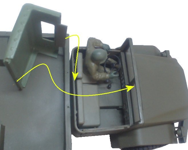
Go ToplessThere is no reason to limit how the truck is modelled by leaving the top on as part of the body.
In fact, having the top removable allows access to the inside of the cab (moving figures, modifications, adding an action camera, etc.).
This is done by ctting along the back of the cab even with the bottom of the side windows, then around the windshield frame. Reinforce the backside of the windshield along the top edge. Reinforce the "canvas" top along the front edge, addin a strip to go under the windshield stiffner to keep the top on. Add a stiffener to the inside of the back of the canvas top, which will fit down behind the seats.
If done right the top will snap and hold inplace (see yellow lines in photo). To remove, slightly pull the windshield top forward and raise the top up.
The chassis will require several modifications. The plastic housings for the WPL steering servo, and reciever circuit will require modification to assomocate the new serov, radio reciever, and speed controller. The chassis will also need modification for the new rear suspension (including adding the second axle).
The
motor/gearbox should be relocated lower (but no
forward or aftward movement) by making
new side plates (copper sheet in photo).
This will not only allow the gearbox to clear
the bed, but also increase the
efficiency of the u-joints which were prone to
come apart by not having such severe angles to
the axles. This does however come a a
cost with a reduction of ground clearance.Also, see photo under: "2. Modifications to the model's radio control and electronics" (below)
Rear Axles
With
the addition of a second axle, there are
several goals. First, the second axle
should be powered to ggive the vehicle the
maximum traction.Second, the axles should act independantly of each other in the vertical direction. This can be described through the diagram at the right.
A. Moving forward on level ground.
B. A bump approaching axle C, where C rides up and D remains on the level ground.
C. As the vehicle moves forward, axle C drops down and axle D rises.
Note that this is for each side, independantly. If the bump is only on one side then the wheelset for that side moves up and down as shown and the wheels on the other side ride level.
Also note that the wheels do not ride straight up and down but on an arc where the center of the arc is the black dot between the axles. This is controlled by the suspension.
The
following is for the drawing at the right:The suspension used on this model was creaded using 3D modeling and printing and is available on shapeways.com
These parts actually fasten tot he WPL axles on the ends of the springs and to the chassis (requiring 2 holes per each side). The tie-bars prevent the axles from twisting.
A second truck or spare axle purchase from a WPL retailer is required. By flipping the axle over, the wheels will turn in the same direction.
You can see where the axle pivot is, the hub under the middle of the leaf spring. The spring has a shaft which goes through a washer and into the axle mount ("T" shaped piece), then through the collar which is pinned to the shaft.
The ends of the springs mount to the axle adapters using pins on each end. The pis fit loosly through the spring to allow the axles to have some slack so the axles can act independantly in respeact to ech other.
The rear axles/wheels will now be 3.00 inches apart, center to center.
Modify the Spare
Tire:
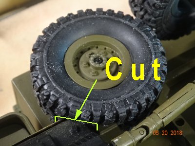 The
spare tire (you can buy extra tires
cheap) is mounted under the right side
near the forward end of the bed.
Space it down about 3/8 inch, making
your own mount. I made mine
incorporation one of the WPL (white
nylon) axle ends so the tire can be
removed by removing the screw (just like
the other tires). The tire needs
to be cut (a small notch) where it
interfeers with the gear box.
The
spare tire (you can buy extra tires
cheap) is mounted under the right side
near the forward end of the bed.
Space it down about 3/8 inch, making
your own mount. I made mine
incorporation one of the WPL (white
nylon) axle ends so the tire can be
removed by removing the screw (just like
the other tires). The tire needs
to be cut (a small notch) where it
interfeers with the gear box.
(See photo, right.)
Add MORE appearance modifications info here.
Move the rear wheels backward 7/16 inch
The
spare tire (you can buy extra tires
cheap) is mounted under the right side
near the forward end of the bed.
Space it down about 3/8 inch, making
your own mount. I made mine
incorporation one of the WPL (white
nylon) axle ends so the tire can be
removed by removing the screw (just like
the other tires). The tire needs
to be cut (a small notch) where it
interfeers with the gear box. (See photo, right.)
Fuel Tank:
The fuel tank is mounted under the
left side near the forward end of
the bed. Make yours to
whatever level of detail youu want.
(See photo, right.) add photo
(See photo, right.) add photo
Steps and Storage Boxes:
The Steps and Storage Boxes are
mounted on both sides of the cab
just under the doors.
Make
yours to whatever level of detail
youu want.
(See photo, right.) add photo
(See photo, right.) add photo
Add MORE appearance modifications info here.
Move the rear wheels backward 7/16 inch
2. Modifications to the model's radio control and electronics
/div>
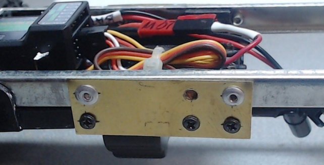
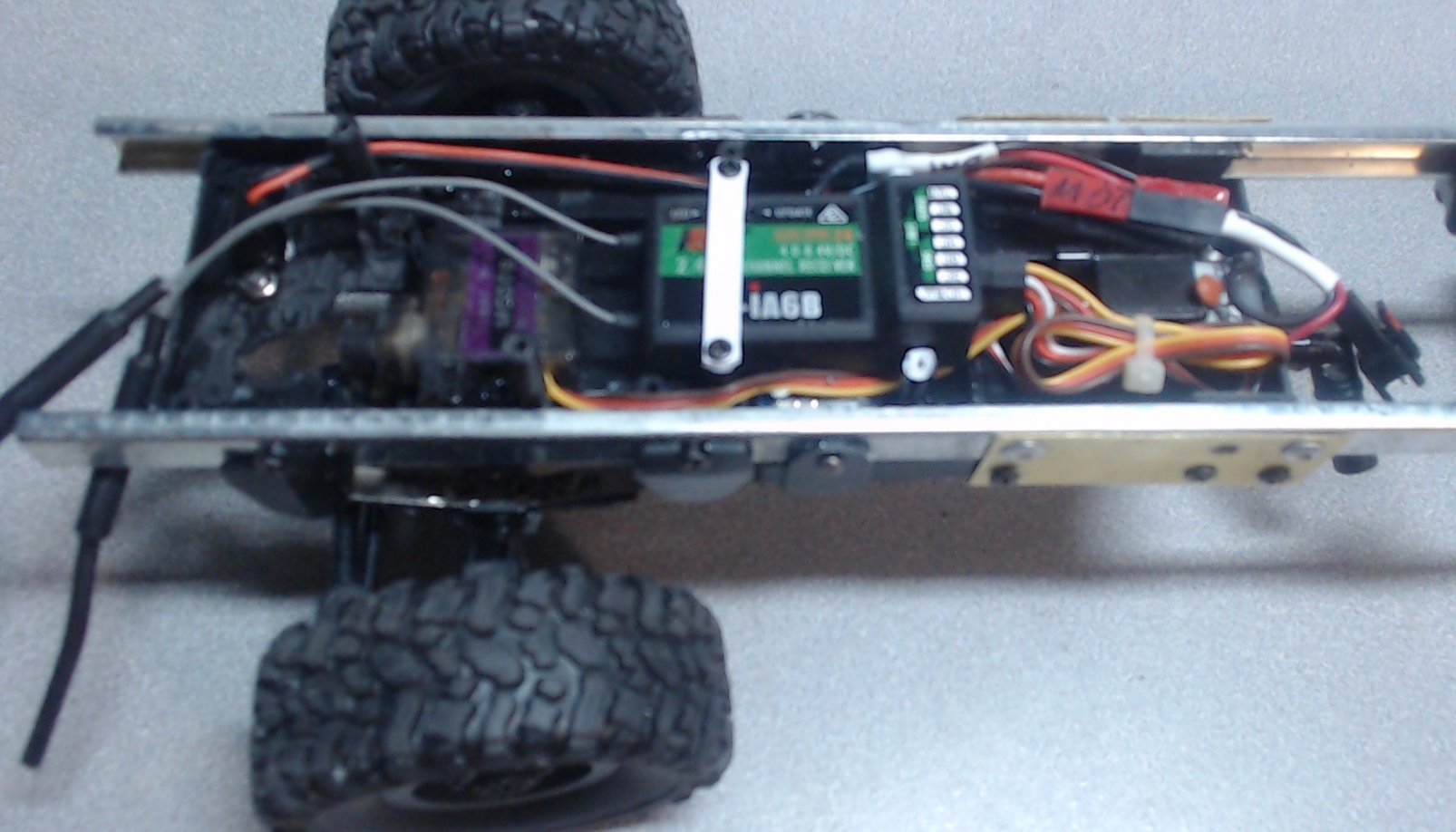 All
of the existing WPL electronics (except the
motor/gearbox) was removed. I added a
new Flysky FS-IA6B 6 channel reciever, a Tower Pro
MG90S metal gear micro-servo for the steering, and a
Hobbypower Rc10aB speed controller (under the
reciever in the photo).
All
of the existing WPL electronics (except the
motor/gearbox) was removed. I added a
new Flysky FS-IA6B 6 channel reciever, a Tower Pro
MG90S metal gear micro-servo for the steering, and a
Hobbypower Rc10aB speed controller (under the
reciever in the photo).
The two reciever antennas will be routed into the cab later.
The existing WPL connector to the battery was removed and soldered to the speed controller's wires. A new connector was soldered to the existing WPL motor to mate with the speed controller.
The new radio, speed controller, and servo greatly improves the performance of the vehicle's steering and speed, especially in the slower speeds.
All
of the existing WPL electronics (except the
motor/gearbox) was removed. I added a
new Flysky FS-IA6B 6 channel reciever, a Tower Pro
MG90S metal gear micro-servo for the steering, and a
Hobbypower Rc10aB speed controller (under the
reciever in the photo).The two reciever antennas will be routed into the cab later.
The existing WPL connector to the battery was removed and soldered to the speed controller's wires. A new connector was soldered to the existing WPL motor to mate with the speed controller.
The new radio, speed controller, and servo greatly improves the performance of the vehicle's steering and speed, especially in the slower speeds.